
One of the ways that heat gets into the helium bath from outside is by thermal conduction. Conduction simply means the flow of heat through a physical object. For example, if you're using a spoon to stir a pot of soup on the stove, the spoon will get hot through conduction. Heat is conducted (flows) from the soup into the spoon and then is conducted up the handle of the spoon to your hand. If you've done much cooking, you may know that silver spoons heat up faster than stainless steel spoons, which heat faster than wooden spoons. These different rates of heating illustrate that silver conducts heat better than stainless steel, which conducts heat better than wood.
One of the ways that heat can be conducted into the XRS helium tank is through the tube we use to fill the tank with liquid helium (the fill tube) and the tube which allows the helium gas to escape (the vent tube). These tubes run from the helium tank, at a temperature of 1.3 Kelvin, up to room temperature, at approximately 300 Kelvin. Goddard Space Flight Center was responsible for building only the sections from the helium tank up to the temperature of the solid neon tank, 17 Kelvin. Even though the "warm" end of our sections of the fill and vent tubes would be held at the temperature of the neon tank, it was still a difficult problem to reduce the heat load to the level we required.
There are 3 common ways to reduce the heat conduction along an object (in this case, along a tube:)
But even if we made it from stainless steel (a material that doesn't conduct heat very well), made it from tubing with the thinnest walls we could manage, and made it as long as we could, it would still have too high a heat conduction.
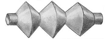
Our solution was to increase the length that the heat had to flow without actually increasing the length of the tubing. To accomplish this seemingly impossible task, we used bellows to make the heat travel a zig-zag path. These are not the familiar fireplace bellows, but they do have accordion pleating like on the sides of fireplace bellows. These bellows look like sections of tubing with corrugated sides. Here's a cross section of a bellows:
 D
D
and a drawing of a bellows:
 D
D
The drawing shows 3 corrugations. The real bellows contained many more, packed tightly together.
Although the bellows successfully reduced the heat flow, they created another problem: they're not as stiff as plain tubing. To keep the tubing from flopping around, we had to create a suspension system of Kevlar (tm) fibers. (Kevlar is a fiber made by DuPont. It is strong and has low thermal conductivity.)
Many devices in XRS low temperature stage need electric power. The wires that carry the power run from the power supply - at room temperature - to the various devices at low temperature. Just as with the fill and vent lines, there is heat conducted down the wires to the low temperature section of XRS. To minimize the heat conduction, we can use the same techniques as for the fill and vent tubes, that is:
Unfortunately, there is another type of heating caused by the wiring, the heating caused by electric currents flowing through wires. The quality of wires that causes them to produce heat is measured by a quantity called resistance. The more resistance a wire has to the flow of electricity, the more heat it produces. Appliances such as electric heaters and toasters are designed to have high resistance to electric current, so that they will produce heat. The wiring in our houses is designed to have low electrical resistance, so that it won't overheat. Interestingly, wires that have high resistance to the flow of electricity also tend to have high resistance to the flow of heat. Wires that are good at conducting electricity (that is, have low electrical resistance) are also generally good at conducting heat.
How do you minimize the electrical heating in a wire? There are three standard techniques:
As you can see, a wire designed for low electrical heating would produce high heating from heat conduction, and vice versa. Is there no way out?
Fortunately, most of the devices in XRS required such low currents that we could use very thin wires and still not have to worry about electrical heating. However, two devices required larger currents. The magnet, part of the Adiabatic Demagnetization Refrigerator (ADR) required 2 Amperes. Two valves (part of the fill and vent line system) required 1 Amp each. To carry electrical power to these devices, we used the only loophole in the relationship that good electrical conductors are good heat conductors. We used superconducting wires.
You can also see a more technical treatment of the high temperature superconducting leads.
For a description of the method used to hold the liquid helium in the tank while letting the helium gas escape through the vent tube, see the Porous Plug section of our Introduction to Liquid Helium page. In brief, there is a porous plug blocking the hole where the vent line attaches to the liquid helium tank. Helium evaporates at the end of the plug in the vent line, producing the cooling effect that keeps the tank cold. (Just as evaporating perspiration keeps us cool on a warm day.) However, liquid helium does not escape through the plug.
At least, not much liquid helium escapes through the plug. In reality, a tiny amount of liquid does get through, enough to form a thin film on the walls of the vent tube. This film flows down the tube till it eventually evaporates and is lost.
The helium film evaporates so far down the tube that it doesn't contribute to keeping the helium tank cold. On previous satellites that used liquid helium coolant, the tiny loss of liquid to the film in the vent line was too small to be worth worrying about. But XRS had such a small amount of liquid helium that we couldn't afford to lose the cooling power of even this tiny amount.
So we designed a heat exchanger to recapture the cooling power. The heat exchanger connects to both the helium film on the walls of the bent tube and the helium tank. The helium film in the tube is cooler, because it's in contact with the evaporating surface of the porous plug. Therefore, heat flows from the (warmer) helium tank to the (cooler) thin film, cooling the tank and evaporating the thin liquid helium film in the tube.
You can also see a more technical treatment of the film killer.
|

|
