This page gives you a look at one of the ways we have worked to limit the heat flowing into the XRS helium tank. As heat flows into the tank, it evaporates the liquid helium coolant. Since we have a limited amount of liquid helium coolant that we can carry, we have worked to reduce the heat flowing to the tank as much as possible.
There are two tubes that run from the XRS helium tank out to the room temperature part of the instrument. One tube is the fill line, the tube through which we pour the liquid helium to fill the dewar. The other tube is the vent line, through which helium vapor escapes to the outside as the liquid helium coolant slowly evaporates.
Both of these tubes run from a low temperature (within a couple of degrees of absolute zero at the helium tank) to a higher temperature (about room temperature at the the other end). Therefore, heat will be conducted (i.e. will flow) from the hot end to the cold end. We see examples of heat conductance often in everyday life. For example, when you poor a cold drink into a warm glass, the heat flows out of the glass into the drink. (In other words, the glass gets cold.) Or, when you're stirring a pot that's heating on the stove, the handle of your stirring spoon can get hot. Heat flows from whatever you're stirring into the spoon, then along the spoon, till it reaches the handle (and your hand.) If you use a silver spoon, it will heat up fast. (Silver is a good conductor of heat.) If you use a stainless steel spoon, it will heat up a lot more slowly. (Stainless steel is a poor conductor of heat.)
There are 3 simple ways to design an object so that it will have low thermal conductance:
Here's what we did at first to hold down the conduction heat load through the fill and vent lines:
But we still calculated that too much heat would be leaking down them. So we used a technique that makes the tubing seem longer to the heat flow without making it physically longer: we inserted bellows into both fill and vent lines. These are not bellows as we think of fireplace bellows. In fact, they are sections of stainless steel tubing. However, their walls have the same sort of accordion fold that you see in the flexible part of a common bellows. Here is a cross section of one of a bellows like the ones that we used.
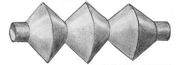
The real bellows have many more corrugations than the 3 shown in the drawing. Here is a drawing of what such a simple, 3-corrugation bellows looks like.
Heat flowing through the walls of the bellows must follow the zigzag path that the bellows take. The distance that the heat must flow is thus much longer than the distance from one end of the bellows to the other. In fact, in a 1-inch long bellows, the heat must flow through a 4-inch long path to get from one end to the other. Thus, using bellows in our fill and vent lines reduces the heat that is conducted along them.
Using the bellows allows us to cut the heat flow through the tubes, but it brings another problem: the bellows are floppy. Since we don't want our tubing banging around during launch, we have braced the fill and vent lines with twine made of Kevlar. Kevlar is a fiber, manufactured by DuPont, which is strong and which does not conduct heat well. The pieces of Kevlar twine run between the tubing and the more solid parts of the XRS cryostat, holding the tubing firmly in place, without appreciably increasing the heat flow.
 Cryogenics & Fluids Home Page
|

|