 D
D
The gas gap heat switch allows us to control the flow of heat. When we need to exhaust heat from the ADR to the helium bath, we turn the switch on. When the transfer of heat to the bath is finished, we turn the heat switch off.
To turn the switch on, we flood the gap between the endpieces with helium. Heat can then flow from one endpiece, through the helium, to the other endpiece, and then out of the switch. The helium is stored in a getter of zeolite. Zeolite is also called "molecular sieve". Zeolite, like activated charcoal, can adsorb large quantities of gasses. The zeolite is held in a small circular chamber. (You can see that chamber on top of the assembled swtich, in the photo, below.) When we heat the getter, the helium vaporizes and flows through the small capillary that connects the getter to the rest of the heat switch.
To turn the switch off, we evacuate the gap between the endpieces. This we do by allowing the getter to cool down. The helium then is readsorbed onto the zeolite. Heat cannot then flow between the endpieces.
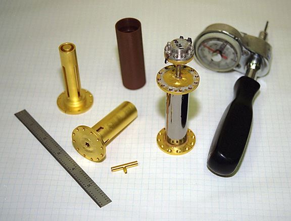
This photo shows some of the parts of the ADR heat switch, along with an assembled heat switch and some tools. Here are the explanations of the pieces, numbered as in the line version of the illustration.
1. Assembled heat switch. The outer shell is covered with shiny titanium foil. The getter chamber is at top, connected to the rest of the swtich by the capillary.
2. Getter capillary. This allows helium to flow between the getter chamber and the rest of the switch. The small side branch is used to flow the helium into the switch: it is closed after filling.
3. End piece. The hole in the center of the near end is where the getter capillary will be attached.
4. End piece (other end). The hollow cylinders of this end piece fit between the hollow cylinders of the other end piece without touching when the switch is assembled.
5. Outer shell. The endpieces (numbers 3 and 4) are epoxied into the ends of this shell. During assembly, technicians align the end pieces so that they do not touch each other. The shell is made of DuPont polyimide resin (trade name: Vespel SP-1). Technicians glue a sheet of titanium foil around the outside of the shell, to stop room temperature helium permeation.
6. Torque wrench. Technicians use this wrench to apply precise amounts of torque when tightening bolts (such as those on the getter chamber.)
Rev. 13 Jan 1999.
 Cryogenics & Fluids Home Page
|

|